SJE LOGO new.gif (4118 bytes)  Sang Jing Electronics Co., Ltd.                 


                                        LIST OF THE CAPACITOR PRODUCTS

SERIES OF CAPACITORS                                                                icon-inquiry form.jpg (2268 bytes)

Picture


Series


Type


Features

Applications


Dissipation Factor(DF)


Voltage
( VDC)


Capacitance
(µF)


Temperature
( º c )


Load
Life

                P7 N04A.jpg (27050 bytes)


N04R


Radial


Non-Polarized


DF
£ 4%(120Hz)


50-100


100-1000


-40 to +85


2000 Hrs

              P5 N04R.jpg (17722 bytes)


N04A


Axial


Non-Polarized

P9 N06R.jpg (26642 bytes)


N06R


Radial


Non-Polarized


DF
£ 6%(120Hz)

                      P11 N06A.jpg (13001 bytes)


N06A


Axial


Non-Polarized

          P13 N10R.jpg (29688 bytes)


N10R


Radial


Non-Polarized


DF
£ 10%(120Hz)


25-100


0.47-1000

                      P15 N10A.jpg (22271 bytes)


N10A


Axial


Non-Polarized

    P17 B03R.jpg (18142 bytes)


B03R


Radial


Bi-Polarized


DF
£ 3%(1KHz)


50-100


1.0-150
                P19 B03A.jpg (9804 bytes)


B03A


Axial


Bi-Polarized

  P21 B04R.jpg (18482 bytes)


B04R


Radial


Bi-Polarized


DF
£ 4%(1KHz)


1.0-220

  
P23 B04A.jpg (3495 bytes)


B04A


Axial


Bi-Polarized

P29 P25 B25R B06R.jpg (27063 bytes)


B05R


Radial


Bi-Polarized


DF
£ 5%

(1KHz)

       P31 P27 B05AB06A.jpg (19065 bytes)


B05A


Axial


Bi-Polarized

P29 P25 B25R B06R.jpg (27063 bytes)


B06R


Radial


Bi-Polarized


DF
£ 6%(1KHz)

B06A_P31_copy.jpg (9294 bytes)


B06A


Axial


Bi-Polarized

       P33 B10R.jpg (29861 bytes)


B10R


Radial


Bi-Polarized


DF
£ 10%(1KHz)


1.0-1000

      P35 B10A.jpg (20693 bytes)


B10A


Axial


Bi-Polarized

P41 P37 B12RB15R.jpg (30422 bytes)


B12R


Radial


Bi-Polarized


DF
£ 12%(1KHz)

P39 P43 B12A15A.jpg (18779 bytes)


B12A


Axial


BI-Polarized

  P41 P37 B12RB15R.jpg (30422 bytes)


B15R


Radial


Bi-Polarized


DF
£ 15%(1KHz)

                                                               P39 P43 B12A15A.jpg (18779 bytes)


B15A


Axial


Bi-Polarized

P03R p45.jpg (8618 bytes)


P03R


Radial


Bi-Polarized (Plain Foil)


DF£ 3~ 5%
(1KHz)


1.0-47

                   P47 P03A.jpg (19103 bytes)


P03A


Axial


Bi-Polarized (Plain Foil)

        
  MET P49.jpg (20911 bytes)


MET


Axial


Axial Tubular


DF
£ 1%(1KHz)


100-630


0.01-10


1000

Hrs

   MEA P51.jpg (75154 bytes)


MEA


Axial


Axial Flat

                       MER P54.jpg (25509 bytes)


MER


Radial


Epoxy DIP Coated


DF
£ 0.1%(1KHz)

                     MEX P57.jpg (55123 bytes)


MEX


Radial


Coating Plastic Case


250v.AC 275v.AC


0.047-1.0
          尚進電子.jpg (76911 bytes)


ERC


Radial


E.R.C Radial Type Capacitors


----


6.3-50


0.1-470


-40 to + 105
ºc


2000 Hrs


icon-capacitors.jpg (2342 bytes) icon-company profile.jpg (2342 bytes) icon-R&D.jpg (6585 bytes) icon-qc.jpg (6378 bytes) icon-factory tour.jpg (7371 bytes) icon-inquiry form.jpg (2268 bytes) icon-home.jpg (1866 bytes)  


USAGE CONDITIONS

The following cautions must be observed when using electrolytic capacitors.

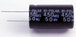
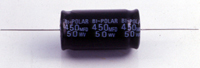
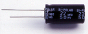
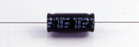
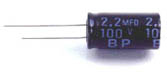
1. DC Electrolytic Capacitors have the polarity.
   
Make sure of the polarity, Application of the reversed voltage may cause a short circuit or
    damage to the capacitors when the polarity is not determined or unknown. Note that DC
    electrolytic capacitors cannot be for used for AC application.

2. Capacitors are not suitable operating with sudden charge
    and discharge are frequently repeated.
   
In the circuit subjected to rapid charge cycles, capacitors may be damaged. Be sure
    and use special capacitors in these applications.

3. Be sure not to apply a voltage exceeding the rated voltage.
   
If a voltage exceeding the rated voltage is applied the leakage current will increase
    which may damage the capacitor. For a short period however the capacitor
    withstands up to the surge voltage.

4. Be sure not to flow excessive ripple current through the capacitor.
   
The flow of ripple current over the permissible ripple current will cause heat of the
    capacitor, which may decrease the capacitance and damage the capacitor. Use
    capacitors designed for high ripple current application.

5. Capacitors should be stored in cold and dry placed which have
     been stored for a long period.
   
The capacitors after long storage tends to have high leakage current which may
    damage the capacitor by the excessive heat because of high leakage current
    flow. Use it after voltage treatment(aging).

6. Be sure of the temperature range.
    The characteristics of capacitors change with the operating temperature. This change
     is temporary and Restorable with in the specified temperature range. Be sure not to
     use capacitors below or over the recommended temperature range.

7. Be sure not to apply excessive force to the terminals and leads.
    The excessive strong force applied to the terminals and lead wires may break them
    and loosen the connections of the internal elements.

8. Capacitance decreases at higher frequencies.
   
The capacitance value is measured at 120Hz. The capacitance decreases as the
    applied frequency becomes higher whereas increases as the ambient temperature
    becomes higher.

9. Tangent of loss angle increases at higher frequencies.
    The tangent of loss angle(tand ) increase as the applied frequency becomes higher
    whereas the ambient temperature becomes higher.

10. Be careful of temperature and time when soldering.
      Dipping must be performed at the soldering temperature or less than 260º c for
      less than 10 seconds otherwise the capacitors may be damaged , and the sleeve
      of the capacitors may deform and crack from the extremely high temperature.

11. Be cautions of cleaning the circuit board after soldering.
     
Cleaning protection for sleeve marking and sealing materials on capacitors body will
      not be damaged, which should never be washed or cleaned by halogens agents or
      solvents such as trichloroethene, Xyiene or acetone etc.

12. The specification of products are according to characteristic (w),
       established by JIS-C5141.

Part Numbering System
When placing an order for Aluminum Elecrolytic Capacitirs,please observe the
following Catalog Part Numbering system which describes how to designate our
product:


1
2
3
4
5
6
7
MR
50V
476
M
8 X 9
---
---
Series
Voltage
Cap
±20%
Size(mm)
Special
Requirements

Example:
MR50V476M8 x 9 m/m(Cass Size)


(1)Series
For a description of our series, please refer to our "Catalog" on page 1.

(2)Voltages

Voltage
6.3
10
16
25
35
50
63
100
®
Code No.
6V3
10V
16V
25V
35V
50V
63V
100V
®

(3)Capacitance
capacitance is shown in micro farads( µf )

µf
0.1
0.47
1
4.7
10
100
1000
10000
Code No.
104
474
105
475
106
107
108
109

(4)Capacitance Tolerance

K
M
Q
±10%
±20%
-10%+30%

(5)Case Size
Case size are in millmeters(mm)-Diameter ( Dø ) x Length(L)
Example:M8 x 9 = 8mm x 9mm

(6)Specail

KTB
Ammo-packing
TR
Reel-packing
LF
Forming and cutting
LC
Cutting
LK
"kink" forming(Snap-in type forming)